
Insanity Too the build
The cars > Insanity Too
Before starting to describe some of the steps we went through building the car, a couple of words of advise if you decide to build a car like this or any other project of this kind;
Planning and budgeting the big items and larger stages of a project like this is relatively simple, what will catch you out is all the seemingly infinite number of small items and jobs that will take up a considerable amount of time and money. All the nuts, bolts, washers and rivets etc. not to mention sheets of aluminium radiator hoses, bushes bearings the list just goes on and on................

Insanity Too, The build project.
As has already been stated elsewhere the I have enjoyed racing in the cross country events it's so much fun even in the old worn out Discovery, I had decided to take it more seriously, I could not afford to buy a serious car so I started planning to build my own car, The demise of Insanity 1 accelerated these plans.
I also get a lot of satisfaction and pride in the engineering challenges this kind of project continually presents.
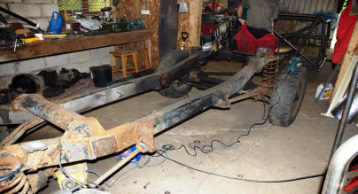
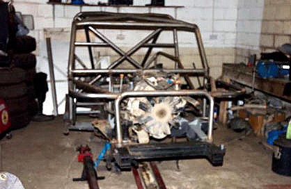
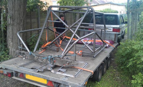
It all starts, with the arrival of the new frame. Roll Over Protection System (ROPS) and body panels at the location we now refer to as the squirrel-pit.
The first job was to remove and "clean" all the unnecessary parts of the chassis, removing the outriggers and various brackets. Its amazing just how much metal we cut off at this point.
Next we located the new ROPS on the chassis to understand where everything was going to sit, We did this many times before we work out where everything needs to go and get an idea of how things will line up.
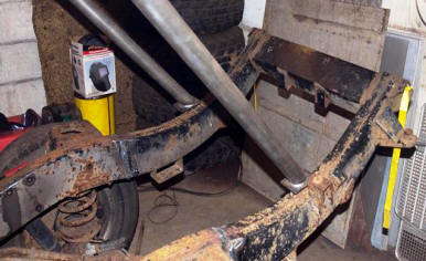
Now we cut out a large section of the rear chassis to eliminate the large rear overhang that a standard Discovery has.
The rear chassis legs and rear cross member are cut off as close to the spring hangers as possible.
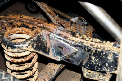
The old rear chassis legs are cut re profiled & welded back on in there new location, to provide the correct support for the rear of the ROPS. We chose to reinforce the joins with the triangular patches.
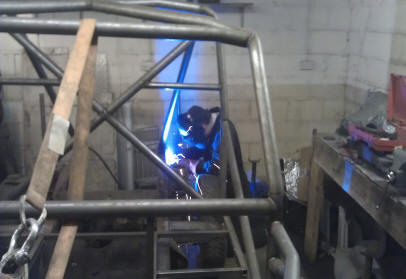
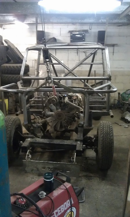
Next we located the new ROPS back on the chassis again and finally start welding it on to the chassis, using ratchet straps to hold everything into place while this work goes on.
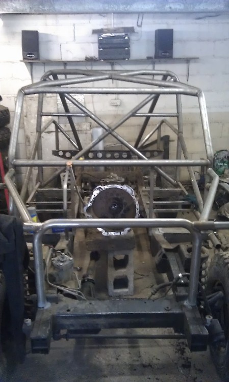
The engine and transmission where relocated into there new position in the chassis and new brackets and mountings made up and welded into place. The new location of the engine was determined simply by swapping the front and rear prop shafts.
Whilst all this was going on the axles have been removed and its all sat on axle stands, hindsight suggests that this should have been done earlier in the project.
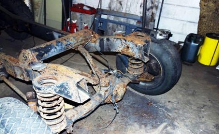
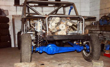
The axles have been rebuilt, replacing the brackets for the radius arms and spring mounts etc. Fitting new bushes throughout.
The hubs and swivels are rebuilt with new bearings, swivel seals and slotted brake disks.
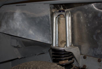
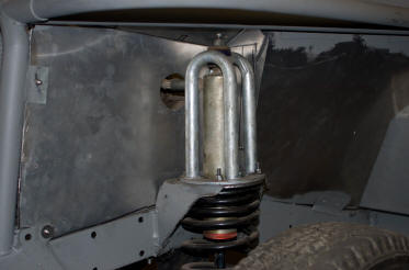
All of this goes back onto the chassis with new springs and using the Milner Varidamp shock absorbers from the original Insanity car (some of the many parts that we recovered from the old car).
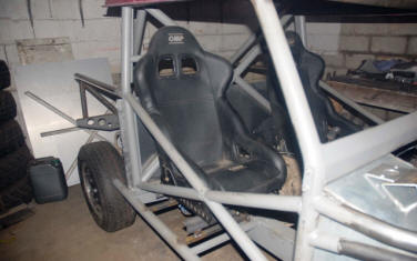
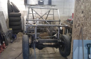
All off a sudden it starts to look like a car again but there's a long way to go. With the axles and some wheels on, things look good.
Back on its “feet” again, you start to get a proper feel for how its going to look and how small it is compared to a standard LR.
The next jobs were to fit the additional cross bars in the doors and fabricate the seat mountings. We went through about five iterations of seat mountings just to get the seats in the best location.
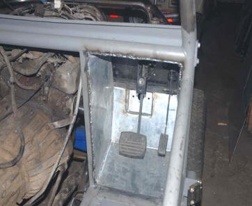
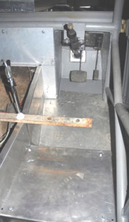
There where also at least three iterations for the foot well construction before I found one I was happy with, this may not be the lightest option but gives a lot of security and mounting opportunities (and will allow me to change the auto pedal box for a manual version in the future). The welding does not look brilliant, this is at least in part because the sheet material is galvanised.
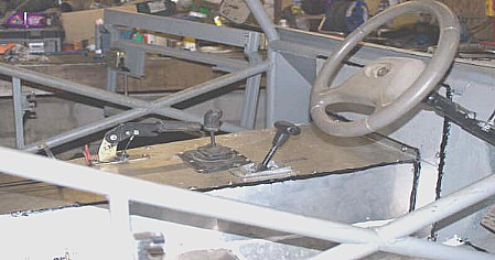
The steering column can now finally be located in place, again not as simple as you might think. The length of the shaft from the steering box influences the location of the bottom of the shaft, but the driving position determines where you want the top end to be.
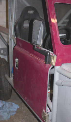
The next job is to start fabricating the floors and transmission tunnel sections. The fabricating of the interior body involved a lot of time staring at large sheets of aluminium wondering how to start. Then another long session with lot of cardboard making templates etc. to try things out. Cardboard is cheap and a lot simpler to cut, This became referred to as the CAD process “Cardboard Aided Design”. We have also hung the doors to enable the door strikers to be located and fitted. The end results are very pleasing, and actually "create" a large open interior space.
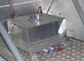
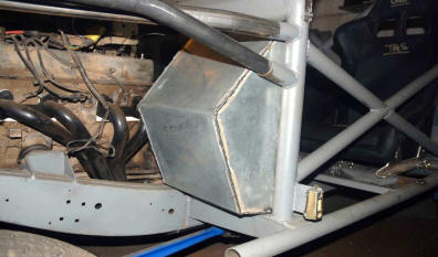
The rear bulkhead panels can just about be made out and the new inner wing panels fitted to the rear "load space". The fuel tank has also been put in place, With the first MK1 version of the fuel system.
The newly manufactured inner wing panels for the front wings, these proved very difficult and time consuming to get right, again with large amount of CAD involved. But the end result creates a neat engine space.
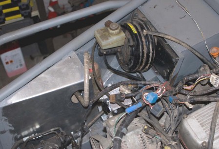
It feels like a long time coming but along with a lot of small jobs like connecting water hoses for the radiator and fitting the PAS reservoir etc. but finally we start putting the major the panels on.
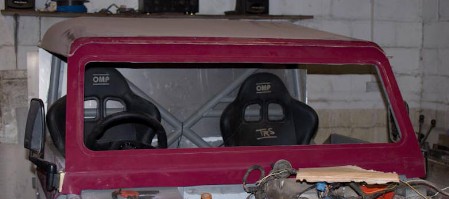
The Windscreen panels fitted and all of a sudden the space inside starts to become "real"
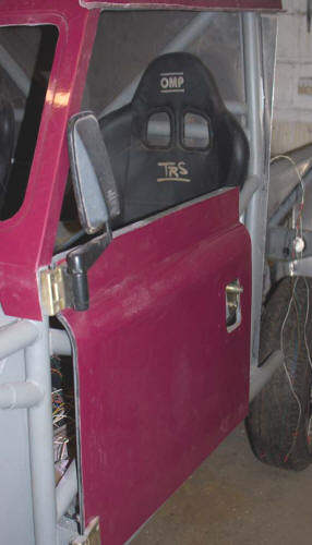
Door panels fitted and door hung in place.
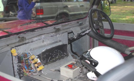
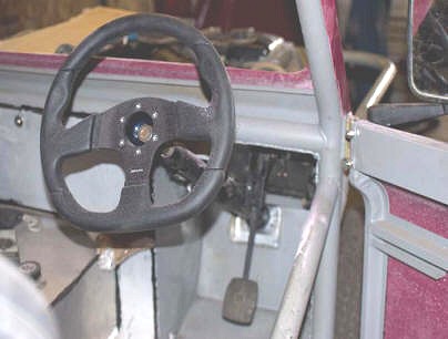
I also made the decision to fit a smaller steering wheel this is a 14" sports wheel with the flat bottom from QT to replace the standard land Rover part.
Not clear from the pictures is that I have changed the pedal box from the auto pedals to a manual pedal box (smaller brake peddle) this is to make any change to a Manual transmission in the future simpler, Well that was the idea anyway!
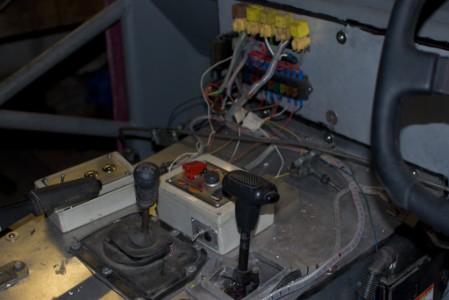
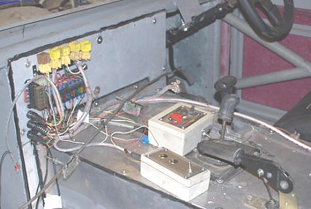
The wiring inside the vehicle is now started, Switches, fuses and relays, and once again it takes several iterations and many days effort to get this correct. (See the final dash layout lower down and even this gets changed again later)
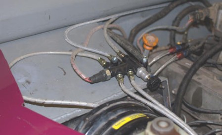
All the Brake pipes and brake balance valve are fitted, all the pipes on this project are Aeroquip braided pipes, made "routing" a lot simpler.
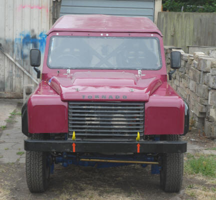
Finally the vehicle is as close to ready as it is likely to get.
At this point we thought there was just some small "fettling" jobs to do but this is very much how the finished car looks.
N.B. Check the ride height as the suspension turned out to be one of the first deliberate design changes, it proved to be too high making the steering very reactive to the "road" surfaces. I changed the springs on the front for shorter stiffer versions, again it takes a couple of attempts to get this so I felt comfortable with the way it worked at speed. Getting the suspension to work properly is one of the biggest ongoing challenges with the car and it will be changed many times over the following years.
The car is ready to race at Radnor July 2013
Or At least I thought so...........
As it turned out I did not get to run the car competitively at this event as the expensive new Bosch 044 fuel pump I am using failed before I got to the start line!