

Engine sump
The cars > Developments and changes > Engines and engine related changes
Engine Sump
Another V8 engine failure.
First a bit of the background as to why we are going to the effort to build a baffled (and gated) engine sump, especially as the construction of this sump became one of the more complex pieces of engineering on the car.
About mid season 2019 at Bovington, we where really enjoying the hard challenging course that had been prepared and the wet conditions made things interesting! We run quite a small cooling pack in the front of the car, and this can collect mud and debris etc. so at the end of the first day we decided to take the car to a quite spot and blast the rad with the jet washer to clean it. It is while driving the car around service area (without a helmet on) that a nasty knock becomes apparent. It is therefore at this point we decide to pack up for the weekend not wanting to do unnecessary damage to the "new engine" little did we know that this would be the end of our entire season!
After removing the new 4.6 engine again and pulling the bottom end apart...........
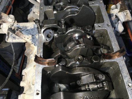
So the big-ends are what can be technically described as "Knackered".
The engine is stripped and the crank sent of to an engineer for assessment.
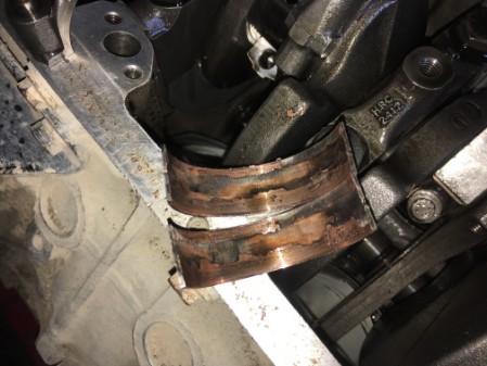
Thankfully the damage to the crank is deemed recoverable with a regrind and oversize shells, however, during the initial check a comment is made regarding the bearing shells;
The bearing shells had "spun" in thebig-end journals, this introduces a risk that the big-end journals in the con-rods may be damaged and oversize. If this is true then the only option at this point would be to obtain a complete new donor engine.
The con-rod and piston assembly's are delivered to the engineers and checked for roundness and tolerance.
The con-rods are deemed to be within tolerance.
The crank re-grind goes ahead and the big-ends in the con-rods are "roughed up" and new bearings supplied.

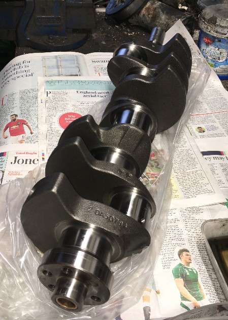
With the crank back the assembly of the engine can commence;
Or so I thought;
On building the engine back up and starting to refit the heads, the head studs started to pullout of the block, so now the engine block goes off to an other engineer to have some Helicoils fitted (to all) the head bolt/stud threads.
Note to anyone that needs to have this done Helicoils are available in multiple lengths make sure that you insist that the longest Helicoils possible are used to get maximum working thread depth, allegedly the shorter lengths can pull out again.
Finally the engine is fully built up, however, the question remains why did the big end shells fail in the first place?
I do not have a definitive answer to this!
Some precautions, however, are being taken on the rebuild;
- Overhaul and replace the oil pump and front timing cover.
- Fit a larger oil cooler.
- And construct a Baffled & Gated sump.
The last item is really what this page is about. I don't know if we had any instances of low oil pressure, we had not seen any evidence on the gauges of presure drop. I don't run a data logger so I dont have any recors. A bit of research quickly comes up with people having issues with the oil moving away from the oil pick-up in the sump during hard cornering on race circuit cars and while we do not experience the same "G" forces as a circuit race car we do subject the car to significant Pitch, Roll & Yaw, so there is a remote possibility that the oil pick up may be uncovered in these extream situations.
Creating a Gated baffled Engine Sump
So why spend so much time and effort to build a baffled sump?
The best option would be a dry sump system, however, these are very expencive and way outside the budget.
The remaining options (for us) where to do nothing and continue to run with the standard Land Rover sump as fitted to the 3.9 discovery engine etc. or to fit a Baffled sump.
There are some very good "off the shelf" motor sport baffled sump options out there, but still a little bit pricey, cheaper than and engine rebuild I will admit.
A lot of research and thinking through the various options, especially when taking into account the forces the car is subjected to, none of the off the shelf option seemed to provide adequate "protection" against the Pitch, Roll & YAW forces a cross county car may be subjected to, so I have decided to try and build my own!
I will freely admit that in designing and constructing the sump baffles, I have taken ideas and concepts from many, many sources combining and adjusting to end up with the solution we finally build, As far as I am aware there is nothing quite like this on other V8's any ware out there, let us know if you have something better!

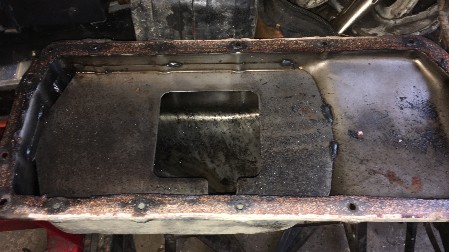
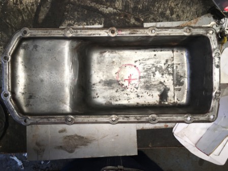
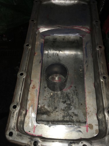
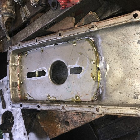
A standard Discovery 3.9 Sump.
The concept behind fitting baffles to the sump is to reduce the movement of oil away from the oil pick up and therefore reducing the potential for loss of oil pressure.
So the process of designing and constructing a Baffled sump;
After some research I decided on several design elements that I wanted to include. I am not going to go into too much detail here as to the reasons as these are quite well documented elsewhere on the internet, however, I will go through the process I went through constructing this sump.
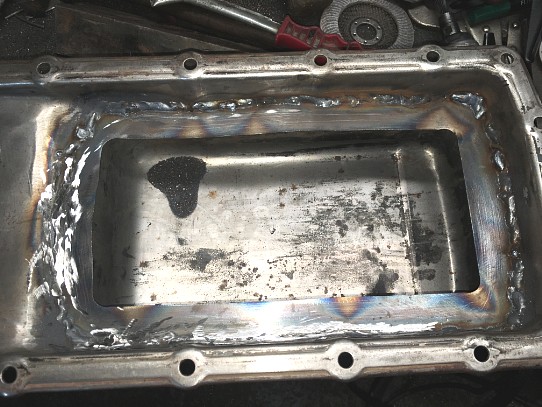
First I removed the standard horizontal baffle from the original sump pan.
My Plan;
As has already been said I am intending to create a gated baffle system. I have also decided to create the centre "Box" on a diagonal, I am hoping that this will be better in an off road environment, as the forces moving the oil around the sump are not purely forward & backward or side to side.
I have also been experimenting with an idea to make the whole assembly removable for maintenance and cleaning etc.
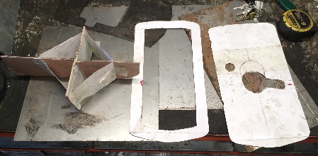
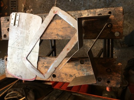
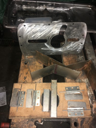
So
everything starts with the CAD (Cardboard
Aided Design)
various different shapes and sizes where tried out before I settled
on the basic templates above. The cross in the middle of the model
was to keep it simple and for stability of the model this will be
discarded during the manufacture of the steel parts.
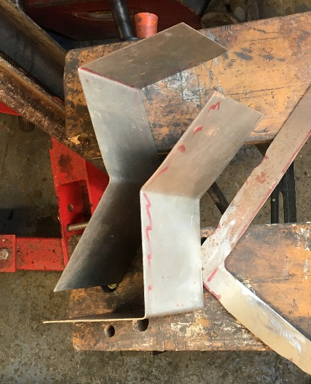
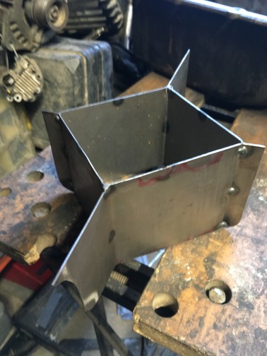
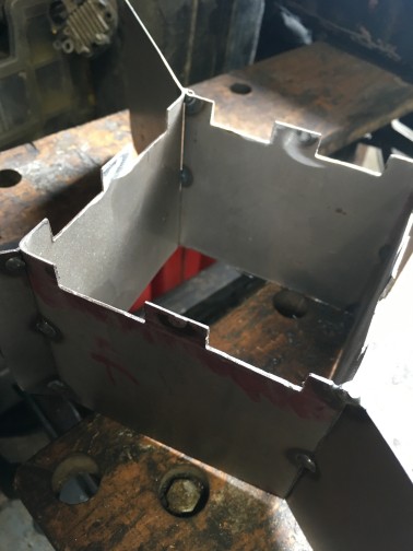
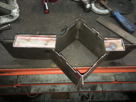
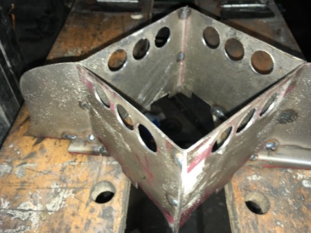
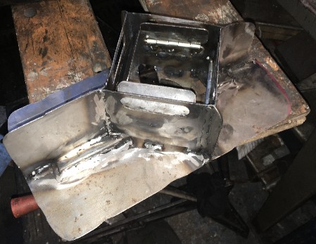
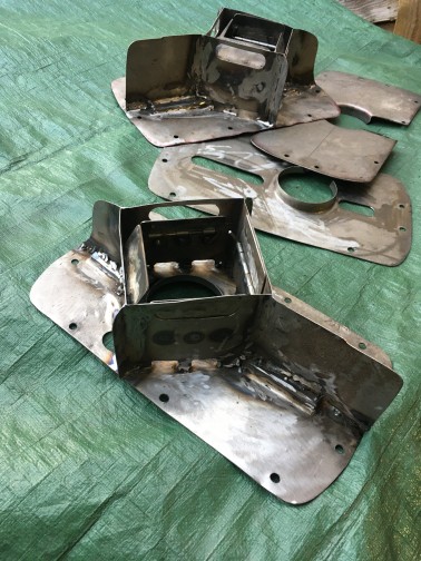
Staring to cut and construct the steel sections that will make up the new baffles. I was really pleased with the two sections that would subsequently make up the baffle box.
The plan (this may always change), is to fit brackets so that the main Baffle and surge plates etc. can be removed for maintenance etc. so initially I have created a ring section that will be welded into the sump that the main section will subsequently mount onto. This may be a bit over the top, but as time went on and the design develops its recognised that this idea may have some other advantages in terms of oil control. The idea being to let oil flow back to the main sump and to trap it there as best as possible.

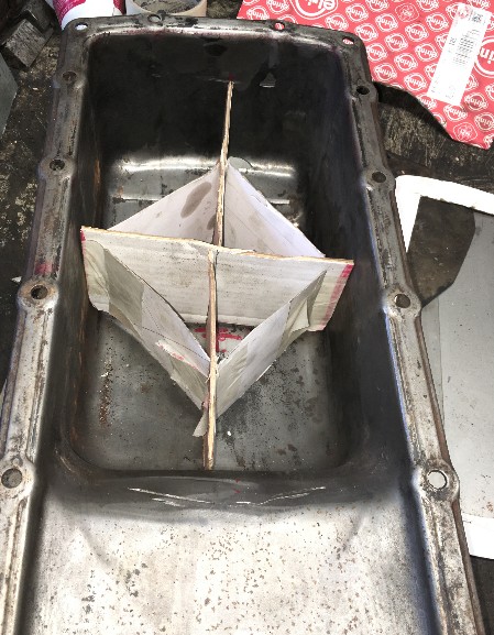
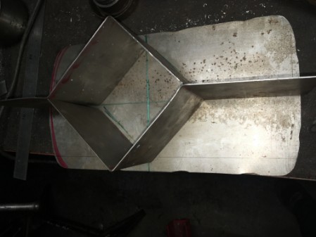
Laying out the basic parts and starting to confirm the location and fit of the different parts.
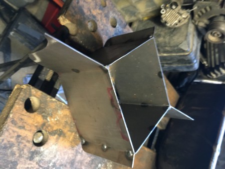
Laying out the basic parts and starting to confirm the location and fit of the different parts.


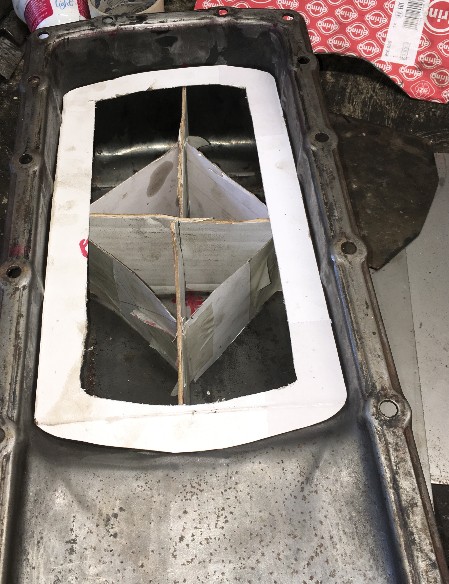
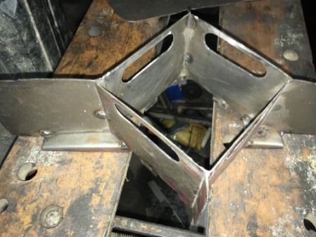
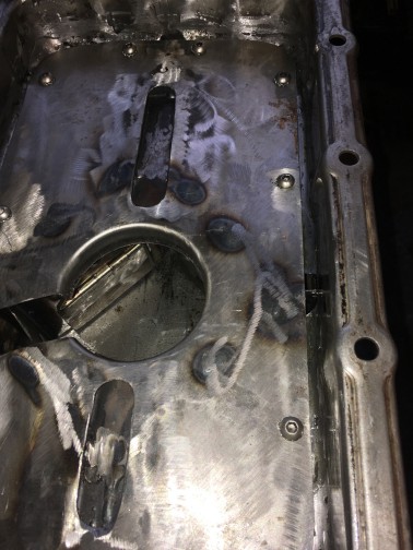
The drain back hole and slot for the oil pick up pipe have been Cut and a flange "Pressed" into the horizontal baffle. The baffle box is tacked into place to enable us to start properly shaping the profiles to make it a good fit to the sump pan.
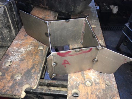
Next Step, I have cut some slots at the top of the baffle box to allow oil to overspill and find a level under static or "calm" conditions
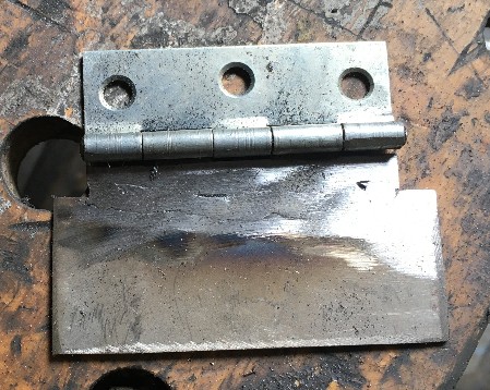
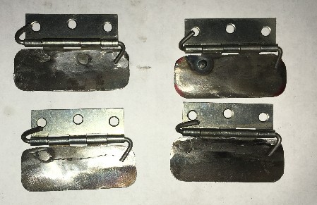
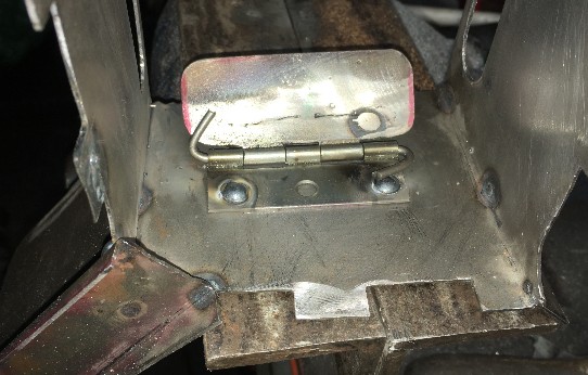
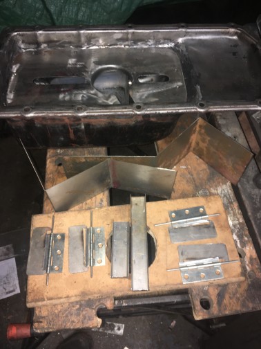
Making up the baffle gates,
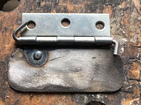
I have started with some standard of the self steel door hinges, however, during the creation of the gatesthere are several changes that will be made. The form of the hinge is changed slightly so that when clamped tight to a surface the hinge will not "bind". One side of the hinge is cut short and some steel sheet welded in place to create the gate surface. Finally I replace the hinge pin with some 3mm rod that can be extended and bent to provide a stop so tat the gates cannot open too far.
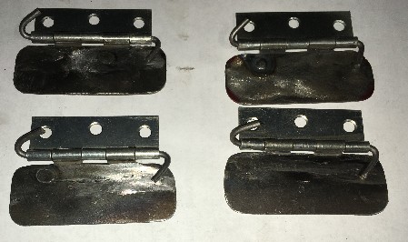
It took several/many iterations and a couple of scrap attempts to get the end result as I wanted it,The photo on the left is the final good example that I hope to copy to make up a set of four, the picture on the right is an early attempt that I was not happy with.
Then below are the completed set of four baffle gates ready to weld into the baffle box.
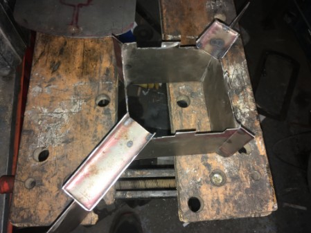
The next step is to create some channels in the horizontal baffle.
To achieve this first I make up a pair of gullies that will run under the horizontal baffel. The intention here is to encourage as much oil as possible to make its way back to the central section of the new baffle arrangement.

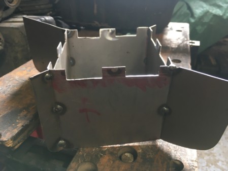
Cutting the holes for the gates, I desided to make these large slots in the end to increase oil flow and finaly starting to fit the gates.

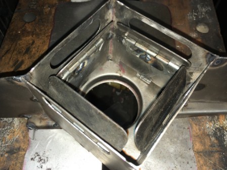
Cutting the drain slots into the top horizontal baffle plate to encorage the oil back to the center of the baffles.
Note the two small holes at each end, the idea is to put everything into the sump pan and when it has all been aligned properly to tack weld through these holes then invert the assembly and weld it all properly.
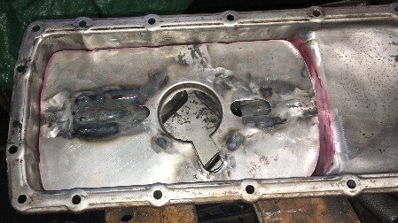
Everything welded together and the full assembly sat in place in teh sump pan.
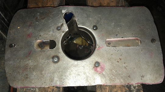
First attempt at fitting the mounting plate that will secure the bafles in place.
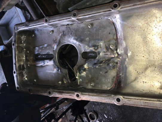
Everything
is finally bolted into place in the sump pan, It was not the
prettiest job but should work......
Or
so I thought, with it all finally assembled, the sump pan and baffle
assembly is located on the engine, It is only now that I find that
something has been measured slightly wrong and it does not fit/locate
correctly on to the engine the oil pick-up pipe will not allow the
whole thing to fit into the correct location.
So having identified the mistakes, the only real option was to start again: with Mk. 2, 3 & 4 until a version has been made that I was happy with and fitted.
So the repeat process went along the lines of;
- Make up new horizontal baffle plate, checking and double checking the dimensions and fit repeatedly. At this point one change I made during the manufacture was to make up a simple bracket to fit on the back of the engine to represent the rear sump wall, this meant that the location was simpler to identify, something I should have done the first time. Again however I still made mistakes and on the Mk2 version I cut the slot for the oil pick up in the wrong place.
- Then I made up the "kit of parts" that will be used to make the baffle walls, gates and channels.
- Shape and profile the new baffles to make a tight fit into the sump pan.
- Finally weld it all together and fit it back into the sump.
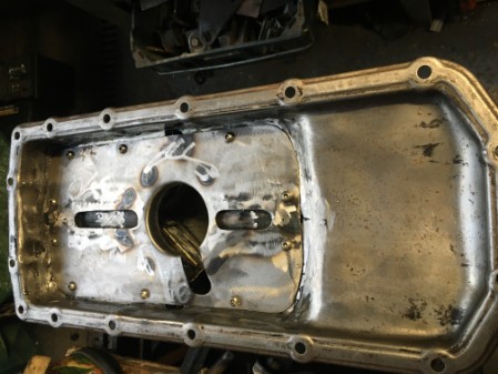
The final fitted gated baffled sump.
One
decision I made during the manufacture of this baffle system was that
I wanted it to be removable to allow repair maintenance and cleaning
in the future. I also wanted to fit some sort of "Windage"
baffle. It was not possible to do this by fixing anything along the
edge of the sump pan in the more conventional way as this would interfere with the removal of the
new gated baffle assembly.
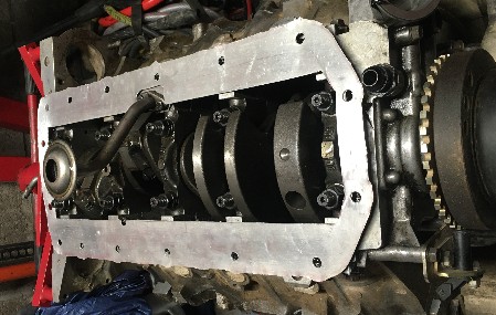
So
my solution has been to create an aluminium sandwich plate fitted
between the engine block and the sump pan.
None
of this has been tested at this stage so I am unable to say if it
works or not or even makes any difference, unfortunately only time
will tell.