

Engine rebuild RV8 4.6 and megasquirt
The cars > Developments and changes > Engines and engine related changes
Another engine, the story.
So here we go again, another new engine, and not making easy on myself I decided to convert the engine management to a Megasquirt system.
Firstly why another new engine? It all started (or ended) on the first racing lap at Bovington towards the end of the 2017 season, there was a very large water splash at the end of the stage and because of this I had decided to relocate the air intake for the engine away from the front of the car to further back in the engine compartment.
This, however, turned out to be a bad decision as the new location still sucked in a considerable amount of water on the first fast pass through the water splash, Hydraulicing the engine.
Over the next weeks Bent con rods where replaced, new piston rings fitted and the engine rebuild stated only to find later that many of the head studs had also puled the threads out of the block.
The engine was deemed scrap.
With only two weeks to the final event of the season I searched the country for a replacement 3.9 engine eventually sourcing one not too far from home, on swapping the front cover (I have modified the oil ways to enable the oil cooler and remote filter to be fitted.) it became apparent that the engine was not all that it was described as, but time being short it was built back up and enabled us to complete the final event of he season and helped us earn the second place overall in the trophy class 2017.
This engine subsequently became known as Franc, short for Frankenstein I'll leave the reasons for this to your imagination.
The following year (2018) the BCCC was cancelled at the last moment, so I decided to take it relatively easy for the year and only enter the Welsh Hill rally (photos etc. in the gallery) This was my first ever Hill rally on what turned out to be a very hot July weekend. This was also to be the end of Franc.
Overheating and burning oil like no tomorrow, leaving a trail of blue smoke behind the car and on the final couple of rounds refusing to idle or even start properly.
A comparison damaged con rod and a good con rod on the right.
The result of Hydraulicing the engine at Bovington.

One of the studs along with the thread that is supposed to be in the cylinder block!
Why change to A 4.6?
Several reasons;
- The 4.6 is cross bolted so should be a stronger bottom end.
- The 4.6 is reported as delivering a lot more torque, I hope the transmission can cope?
- Buying and scrapping a cheap RR P38 was a relatively easy way to got hold of a donor and scrapping and selling the rest of the car paid for itself.
- I decided that being 4.6 I would get a sleeved block so the cost was much the same regardless of engine choice.
Why go to the trouble of installing a Megasquirt?
Basically the standard 4.6 engine management is massively complex and I was not convinced the old 14CUX was up to the job.
So at the end of 2018 after various delays due to family traumas the basic parts/kits are ordered
- A 4.6 exchange sleeved, short engine from ACR.
- A Semi sequential MS2. from ExtaEFI
- An electric water pump.
- Assorted other parts from all over the place...


The Engine
A couple of changes to the standard 4.6 configuration;
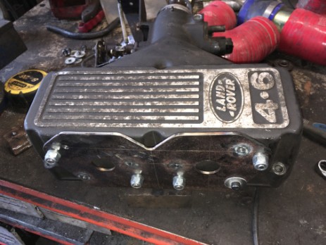
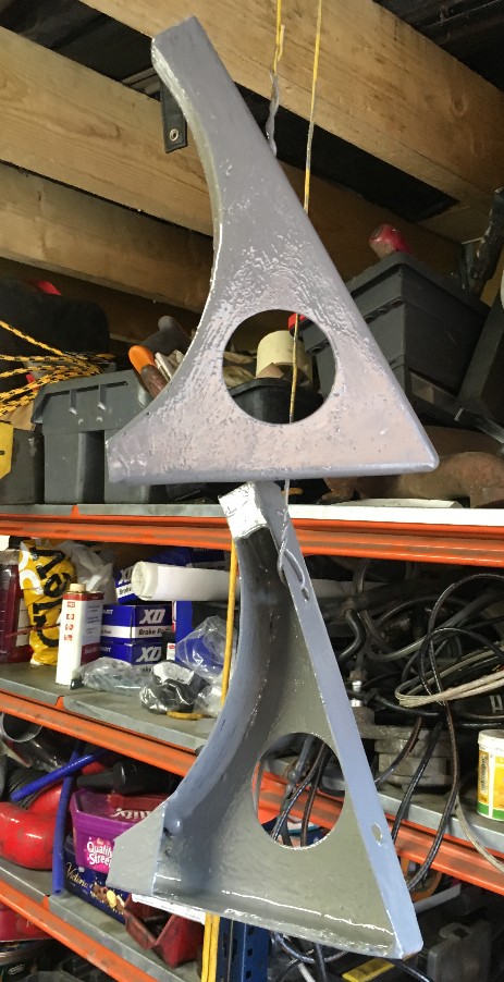
- I wanted to reuse the front cover from the 3.9 engine as the oil ways are more suited to the application.
- In the 4.6 standard front cover the oil pressure relief valve dumps into the top of the oil filter housing and the oil filter housing itself is in a slightly different location.
Both of these are important in this build as the front axle gets very close to the engine at this point, to the extent that in the past when I was using a sandwich plate it came into contact with the axle. I have also modified the front cover slightly so that oil pipes are fitted directly to the oil ways.
I have also chosen to reuse the camshaft from the original 3.9 engine that got damaged at Bovington, this also helped drive the decision to reuse the 3.9 front cover.
This meant that I have had to make up/change the camshaft retaining plate as the 4.6 uses a half moon shape that is not compatible with the earlier camshaft (the very early cam shafts did not use any retainer, relying on the timing chain to keep everything lined up.)
I made up a home made "Dumpy Disy" to block the distributor hole, out of an old distributor case.
The Impeller has been removed from the mechanical water pump and the thermostat removed as part of the electric water pump fitments.
Finally using the 3.9 front cover meant that the alternator and PAS pump all remain in the same configuration.
The Megasquirt project
What I got in the package;
- The ExtraEFI MS2 semi sequential ECU
- Two VAG coil packs, & Electrical Plugs
- Extended wiring loom
- Trigger wheel
- Haul sensor & Bracket
- Air Temp sensor (this I had to replace later)
- Coms cable.

- What I needed to source elsewhere
- The "Stubby" From megasquirtV8, a fabricated tube to support the temp sensor, I then found the temp sensor screw threads where different and needed to replace this as well.
- Plug Leads, from Magnicor
- Coil mounting bracket, I made this up myself as most of the pre fabricated options where not going to fit the mixed 4.6 & 3.9 parts on the engine.
- A water proof box to house the ECU etc
- A number of junior power connectors
- An additional fuse box and relay (with relay socket)
- And I liberated some parts from an older engine loom.

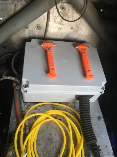
ECU location
The
first job was to install the box into which the ECU Main relay and a
fuse box will fit.
The
box containing the ECU etc will be located toward the rear of the
cabin and takes up a lot of space.
I
have used the fuel pump relay feed from the ECU to control the "Main
Relay" that powers a distribution fuse box (6 way) this will
feed the coil packs and the injector supplies allowing each channel
from the ECU to have its own power fuse.

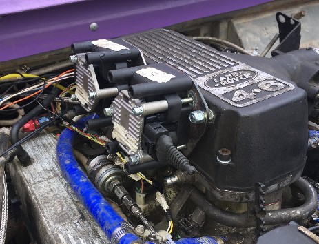
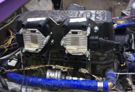
Coil location and mountings
After much deliberation and experimentation with various locations, Including investigating the option of mounting the coils on the chassis/frame, we decided to make up a steel plate that will mount the coils this is then to be bolted onto the Plenum chamber.
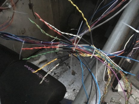
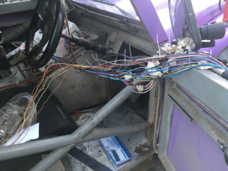
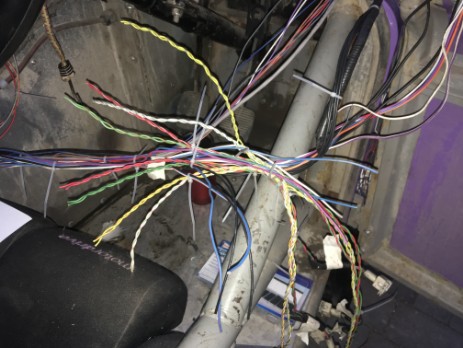
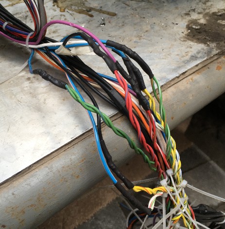
Engine loom
Building the loom takes a long time and repeated iterations of fitting and removing, establishing wire runs and routes, making joints and fitting the various plugs and connectors. Making sure that the connections and wires are good at each stage. This is sometimes made more difficult as he wires are labelled at the ECU end and some are the same colour.
Identifying and joining the injector cables is complex with four signal wires from the ECU, four power feeds from the fuse box and a total of sixteen wires from the injectors all must be matched and joined correctly.
Lots of cable ties make for a relatively tidy job until the final assemble can be taped up.
Finally the plug lead lengths are calculated and the leads ordered.
This however was not without its issues as later I realised that there was a difference between my plan and the instructions for setting up the coil sequences, Thankfully it turns out the planned lead lengths are interchangeable.
The firing order for the rover V8 is; 1,8,4,3,6,5,7,2.
Using the VW, Audi Coil packs .The Megasquirt documentation show the coil connections and firing sequence as
Using the VW, Audi Coil packs .The Megasquirt documentation show the coil connections and firing sequence as
Coil 1Spark "A" Plugs cyl 1 & 6Spark "B" Plugs cyl 5 & 8Coil 2Spark "C" Plugs cyl 4 & 7Spark "D" Plugs cyl 2 & 3
Based on the firing order above this means the coils fire 1A, 1B, 2C, 2D, 1A,1B, 2C, 2D. I.E. each coil fire both halves then passes on to the next coil. An alternative sequence is as follows?
Coil 1Spark "A" Plugs cyl 1 & 6Spark "C" Plugs cyl 4 & 7Coil 2Spark "B" Plugs cyl 5 & 8Spark "D" Plugs cyl 2 & 3
This means that based on the firing order above the coils fire 1A, 2B, 1C, 2D, 1A, 2B, 1C, 2D. I.E. each coil fires once then passes on to the next coil.
After all that it turns out that apparently it makes no difference!

An electric water pump
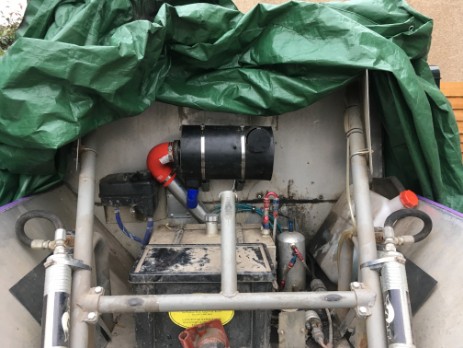
Space to locate this pump was surprising difficult to find. I wanted to located the pump in the lower radiator hose and feed back into the mechanical water pump body.
The Impeller has been removed from the pump and right or wrong I opened up the port in the back of the old mechanical pump to improve water flow.
Again after much deliberation and experimentation a bracket to support the pump is made up and located on the front chassis leg, just behind the PAS box.
The end results are very pleasing with an "interesting" route out of the electric pump into the pump housing on the engine.
Getting the engine started, running.
Once the majority of the components are built up, plumbed in and connected it's time to try and start the engine.
First power up the ECU and try and connect with the laptop to interrogate and copy the base tune settings provided. This typicaly was not strait forward as I could not get the laptop to talk to the ECU, after some investigation and experimentation I found that for the laptop I was using I needed to download and install some software for a serial to USB converter, even though I had ordered an ECU with USB coms cable it still required the
connector conversion software installed as part of the USB drivers.
connector conversion software installed as part of the USB drivers.
Once coms is established I take two copies of the base ECU configuration, one I save as a baseline back up the other I use for the "Tune" I.E. calibrate the TPS.
The next amin task is to remove the spark plugs and crank the engine to get oil pressure, refit the spark plugs;
Switch on the power and press the start button.....................
The engine coughs and sputters, pops and bags but will not fire properly. I spend almost an entire day going through every thing checking and double checking, including trying to check and change the ECU settings with no success, so I pack up and retire for the night to re read the manuals search the internet for answers etc.
Over night I recalibrate the Coolant temp sensor and the air temp sensor and feed the results back into the ECU.
The result of the investigation and additional checks, is that is suspect that the Crank sensor is wired backwards, ( I had not even realised there was a right and wrong way. This was changed and the next day, I recheck the ignition advance at cranking (with the plugs out) and find that its almost 10Deg. out.
Make he changes in the ECU again ("Tooth #1 Angle").
Switch on and press the start button.
This time the engine starts and runs, very briefly a couple of seconds, but it started and sounded good.
So now its back to tidying everything up and finishing all the items that where deemed non essential to the initial run of the engine.
- Tidy and wrap the new engine loom.
- Re fit the plenum properly, it was just fitted in place without sealing etc to ensure that every this worked.
- Fit a Lambda boss in the exhaust to allow the car to be tuned.
- Fit the new air box, I was recommended, very strongly, to use a paper air filter and not any of the "high flow” motor sport filters available. so I obtained a Series V8 air box.
- A number of other details like refitting the fire extinguisher and life hammers somewhere still need to be sorted.
There is also the minor detail of working through the Megasquirt start up manual (and other s) with a lot of base settings that still need to be checked and adjusted....
So the engine started.
Time to take a step back and start on the outstanding work!
Fit the boss into the exhaust for the Lambda sensor, I don't plan to use this for the MS2, however it is required to get the engine tuned. Start making up the brackets for the new air box. Fit the airbox.
And set up the base timing (set the first toothangle correcctly#)


New airbox brackets completed and finaly the airbox located in its new position.
Note
on setting up the base timing setting;
I
had a lot of trouble trying to set-up the base setting to get the
timing marks to synchronise with the ECU settings. After getting
really strange results and timing figures of 60 degrees advanced
(totally unreal) I was advised that the "Programmable"
timing light I had been using was probably not compatable with
the wasted spark set-up being used. I purchased a cheap fixed timing
light and immediately got better results. It was still fiddly to get
the timing mark synchronised, however, I finally got it with the fixed
timing @12 degrees and the first tooth angle # at 41 degrees.
The
engine now runs and sounds quite good even knowing that both the
ignition maps and fuelling maps need attention.
The
car has been book into be tuned on a rolling road so hopefully this
will be a simple fix now.